Creating Retinotopic Mapping Stimuli
This tutorial shows how to create angular and eccentricity stimuli for the retinotopic mapping of the visual cortex. It also demonstrates how to wait for an input trigger and send some stimuli information to an external device through a USB-to-Serial port.
Step 1: Creating the Experiment Hierarchy
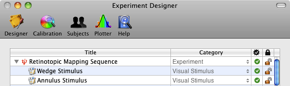
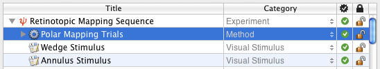
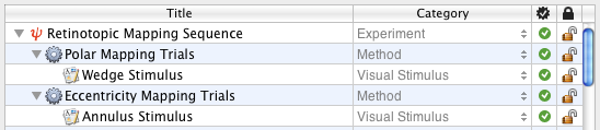
First, create the above events hierarchy in the "Experiment Designer" panel (see the "Contrast Sensitivity: Lesson 1" or "Orientation Discrimination: Lesson 1" tutorial to learn more about how to create this events hierarchy). The hierarchy specifies an experiment that simply shows two consecutive stimuli, a wedge stimulus used for polar angle mapping followed by an annulus stimulus used for eccentricity mapping. These stimulus events still need to be customized in terms of their spatial and temporal properties as detailed in the steps below.
Step 2: Creating a Wedge Stimulus
Edit the properties of the Wedge Stimulus event: select the event in the designer panel and click on the Inspector button (or press Apple-i). In the properties panel that opens:
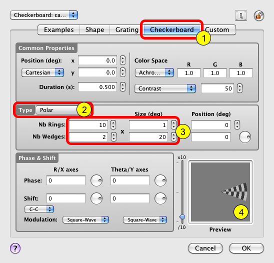
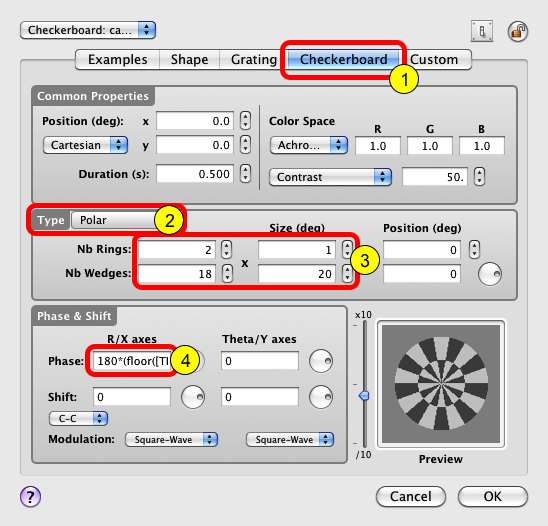
1) Click on the Checkerboard tab to select the "Checkerboard" category,
2) Select the Polar option in the Type pop-up menu,
3) Specify the size of the wedge in terms of its radial range (10 rings 1 deg thick each) and angular range (2 angular sections 20 deg wide each),
4) An updated preview of the stimulus is always displayed in the Preview box.
Step 3: Adding a Counter-Phase Flickering Component
Counter-phase flickering checkerboards are often used in brain imaging experiments to maximize evoked brain activity. Here we will create a counter-phase flickering wedge by reversing the spatial phase at a frequency of 2 Hz for a duration of 5 seconds.
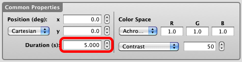
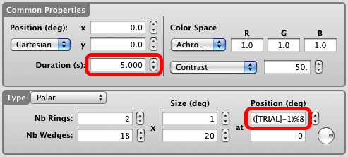
First, increase the stimulus duration to 5 seconds in the Common Properties section.
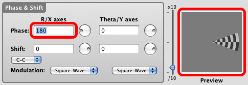
The spatial phase of the wedge can be reversed by specifying a value of 180 deg in the R/X axes Phase text field as illustrated on the figure. Note the phase change in the preview compared to the one in the previous step.
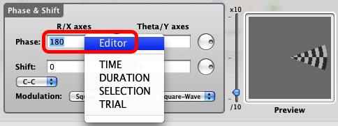
The counter-phase flickering wedge can be created by specifying a phase that changes between 0 and 180 deg over time. To do so you can either edit directly the phase text field and enter the following expression: 180*(floor([TIME]*4+1)%2), or use the expression editor by control-clicking on the text field and selecting the Editor option in the contextual pop-up menu.
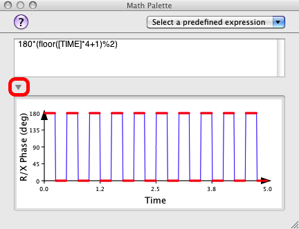
If using the editor, enter the same expression (180*(floor([TIME]*4+1)%2)) in the text field and click on the small arrow to reveal a graphical representation of the time-varying expression. This expression specifies a spatial phase that starts at 180 deg and switches between 180 and 0 deg every quarter of a second (the flicker cycle being 0.5 seconds, hence the 2 Hz temporal frequency).
Note that in the above expression [TIME] represents the built-in time variable relative to the stimulus onset and has to be specified in uppercase because it is a system-defined variable. The % symbol is the modulo operator used to create a sequence of 1 and 0 values.
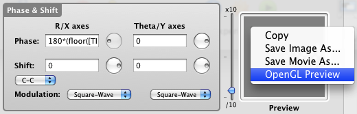
At this stage, you can already preview the counter-phase flickering wedge stimulus by control-clicking inside the preview and selecting one of the options in the contextual pop-up menu.
Step 4: Adding a Rotation Component
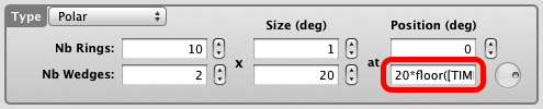
To perform the polar angle mapping, the wedge stimulus has to rotate in discrete steps with the same step size as its angular sections at any given speed. To do so set the Duration text field to 18 s and enter the expression 20*floor([TIME]) in the Wedge Position text field.
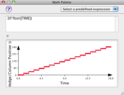
If you visualize this expression in the mathematical editor, you can see that we specified a wedge rotating at a speed of 20 deg per second for a total duration of 18 seconds corresponding to a 360 deg rotation.
If you preview the stimulus, you should obtain the same rotating and flickering stimulus as in the movie above.
Click on the OK button to validate the changes and close the properties panel for the wedge stimulus.
Step 5: Creating an Annulus Stimulus
Edit the properties of the Annulus Stimulus event: select it in the designer panel and click on the Inspector button (or press Apple-i). In the properties panel:
1) Click on the Checkerboard tab to select the "Checkerboard" category,
2) Select the Polar option in the Type pop-up menu,
3) Specify the radial range (2 rings of 1 deg thick) and the angular period (18 angular sections 20 deg wide each) of the annulus stimulus,
4) Enter the expression (180*(floor([TIME]*4+1)%2)) in the R/X axes Phase text field as we did for the wedge stimulus to create counter-phase flickering.
Step 6: Adding an Expanding Component
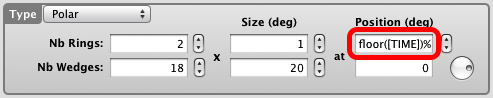
To perform the eccentricity mapping, the annulus stimulus has to expand in discrete steps with the same step size as its rings and to reset to its initial position after it reaches a maximum eccentricity. To do so set the Duration text field to 16 s and enter the expression floor([TIME])%8 in the Ring Position text field.
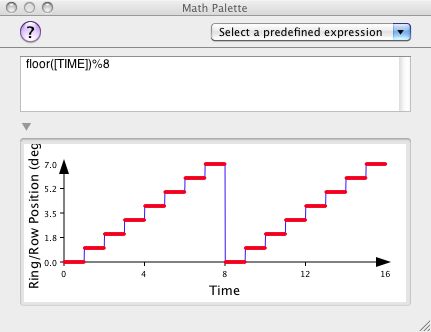
If you visualize this expression in the mathematical editor, you can see that we specified an expanding annulus at a speed of 1 deg per second starting at the display center (0 deg) and ending at 7 deg of eccentricity. The annulus position is reset every 8 seconds and the mapping sequence consists of two cycles for a total duration of 16 seconds.
If you preview the stimulus, you should obtain the same expanding stimulus as in the movie above.
Click on the OK button to validate the changes and close the properties panel for the annulus stimulus.
If you run the experiment now, the two mapping sequences will be displayed sequentially.
Step 7: Creating the Trial Sequence
So far we have created mapping stimuli that automatically progress through the mapping sequence. We need to replace this automatic sequence by a step by step triggering of a trial sequence. Each step of the sequence (angular step for the polar mapping and radial step for eccentricity mapping) will be associated with a trial triggered through self-paced keyboard inputs (eg: 'space bar').
Add a folder event at the top of the design hierarchy, set its category to Method and rename it Polar Mapping Trials.
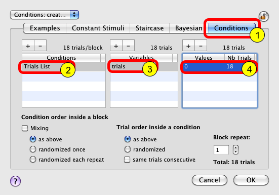
Select the Polar Mapping Trials event and click on the Inspector button (or press Apple-i). The panel above will open. Click on the Conditions tab to select the trial design method (1). Add an entry in the Conditions table and name it Trials List. Select this condition and add an entry in the Variables table. Name it trials. Select this variable and add an entry in the Values/Nb Trials. Set the value of this entry to 0 and the number of trials to the number of steps for the polar mapping (eg: 18 for a 360 deg mapping for the polar stimulus defined in step 2). This simply creates a list of 18 trials to be used for the polar mapping sequence.
Click on the OK button to validate the changes.
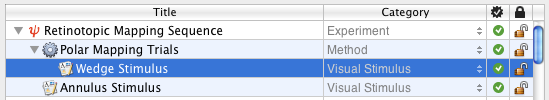
To associate the trials list to the mapping stimulus, move the Wedge Stimulus event inside the Polar Mapping Trials as illustrated.
Now that the mapping stimulus is associated with a number of trials, one has to specify the properties of the mapping stimulus as a function of the trial index: this is achieved by using the built-in variable [TRIAL] which provides the index of the current trial (starting from 1).
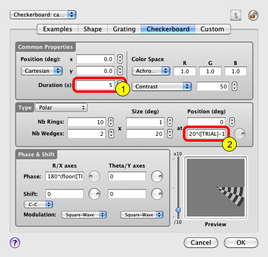
Select the Wedge Stimulus event in the designer panel and click on the Inspector button (or press Apple-i) to edit its properties. Then make the following changes:
1) Set the stimulus duration to a value higher than the expected trigger period (eg: 5 seconds)
2) Change the wedge position to: 20*([TRIAL]-1)
The wedge angular position is now under the control of the trial index rather than being intrinsically time-varying. However the resulting stimulation is identical to the one obtained from step 4 above if each trial is presented for 1 second.
Click on the OK button to validate the changes.
Repeat the above step for the eccentricity mapping so your design looks like this one:
1) Create a trial design method named Eccentricity Mapping Trials with 8 trials corresponding to the number of radial steps for the eccentricity mapping sequence defined in step 6.
2) Move the Annulus Wedge Stimulus event inside the Eccentricity Mapping Trials to associate this trials list to the mapping stimulus.
Do not forget to modify the properties of the Annulus Stimulus so the annulus position is linked to the trial index through the expression: ([TRIAL]-1)%8. Click on the OK button to validate the changes.
If you run the experiment now, the two mapping sequences will be displayed sequentially for one cycle each, each step displayed for 5 seconds. You will notice that the sequences run without user interaction or triggering inputs.
Step 8: Triggering the Trial Sequence
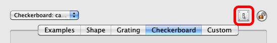
To replace the automatic sequence with a step by step triggering, one simply has to change the default behavior for the stimulus offset. To do so, edit the properties of each mapping stimulus, and click on the small switch icon in the top right-hand corner of the properties panel.
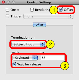
This opens a palette entitled Control Settings which provides further settings for various aspects of the stimuli presentation:
1) Check the Offset box to access the offset options,
2) Select the Subject Input option in the Termination pop-up menu to indicate that the stimulus display should terminate when an input is detected,
3) Choose Keyboard as triggering/input device, and specify the key to be pressed as triggering input (eg: SB for 'space bar'). Optionally you may indicate to wait for the input release before the stimulus offset occurs.
Click on the OK button of the properties panel to validate the changes (this also closes the Control Settings palette). Again, make sure this is done for both wedge and annulus stimuli.
Run the experiment to check that the mapping sequences progress smoothly with each keypress.
Step 9: Sending Stimulus Information to an External Device
Now that we have a working mapping sequence, one may decide to send some stimuli information to an external device at the onset of each step of the sequence. For example, this information could be used as markers for EEG recording to help segment the EEG signal. We illustrate this triggering output through a USB-to-Serial port.
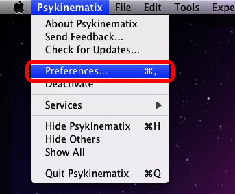
First, we need to configure Psykinematix to support communication through the USB-to-Serial port. This is done through the Psykinematix Preferences menu:
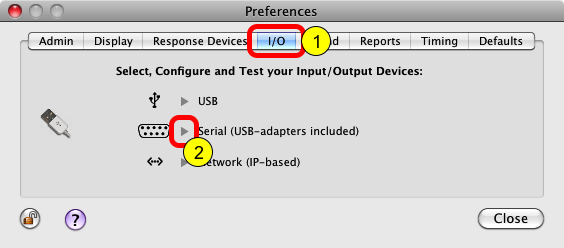
1) Click on the I/O tab to access the input/output preferences,
2) Click on the small arrow for the Serial devices. This opens a panel that lists the available serial devices.
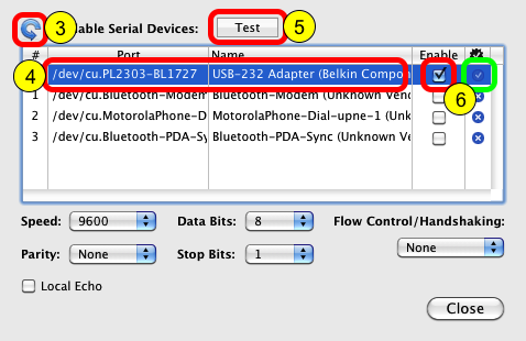
3) Click on the Rescan button to update the list of available serial ports,
4) Select the serial port you wish to use (eg: a Belkin usb-to-serial adapter),
5) Click on the Test button to test the communication with the selected port,
6) On success, a blue check mark appears in the right column of the device list. You can then enable the port by checking the box in the Enable column.
You should also refer to the documentation of your external device to find out the correct configuration of the serial port (speed, parity, etc).
Close this panel and the Preferences window, and return to the designer panel.
Secondly, we need to configure the experiment properties to indicate which device to use for serial communication:
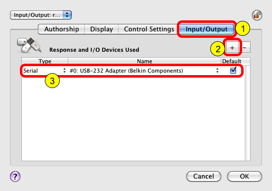
1) Select the experiment event Retinotopic Mapping Sequence, click on the Inspector button (or press Apple-i), and select the Input/Output tab,
2) Click on the + button to add a I/O device,
3) Select the Serial option from the Type pop-up menu, choose the serial port you wish to use and check the Default box.
Click on the OK button to validate the changes.
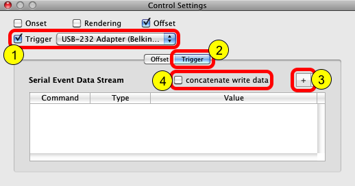
Finally, we can specify the stimuli information to send to the external device. To do so, edit the properties of each mapping stimulus, and click on the small switch icon in the top right-hand corner of the properties to open the Control Settings palette. In the palette:
1) Check the Trigger box and select from the pop-up menu the same serial device that you added above under the Input/Output tab of the experiment properties,
2) Select the Trigger tab to access the table that specifies the stimuli information to be sent,
3) Click on the + button to add any information you wish to send through individual serial 'write' commands (each information is converted to an ascii string before being sent). See below for examples of information that can be sent,
4) Optionally all information can be concatenated into a single 'write' command by checking the concatenate write data box (the various information are then sent separated by a comma).
Once all required data has been added to the table, click on the OK button of the properties panel to validate the changes. Again, make sure to specify the output information for each wedge and annulus stimulus.
It is important to note that the output information is sent to the serial device at the onset of the visual stimulus. In this tutorial, the information is sent at the onset of each step of the mapping sequences.
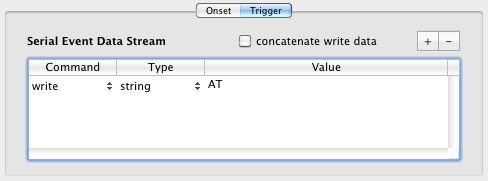
The simplest information you could send to the output device is a command without argument, like the 'AT' ASCII command in this example.
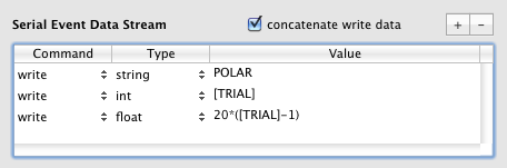
You can also send information about the mapping sequence ('POLAR' or 'ECCENTRICITY' string), the trial index ([TRIAL] as integer value) or the stimulus position as a float value. When the value consists in an expression containing variables, the expression is evaluated based on the current values of the variables and the result is converted to the specified type (int, float, etc.) before being sent as a ASCII string.
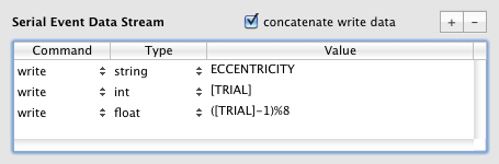
If the concatenate write data box is checked then a single write command is sent, for example for the first trial of the eccentricity mapping sequence: write "ECCENTRICITY,1,0."
You should refer to the documentation of your external device to find out what commands are valid and what the format of their arguments is.