Calibrating your Experimental Display
This step-by-step tutorial teaches you how to:
1) perform the calibration of your experimental setup using Psykinematix.
2) specify a calibration configuration for a given experiment.
To learn more about the calibration panel, see the Calibration chapter.
Preparation
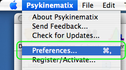
First, open the Display Preferences panel to specify the default display and settings you wish to use when creating new experiments.
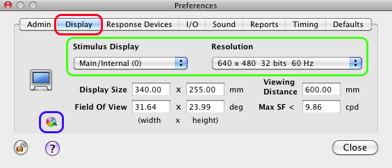
Click on the Display tab to select the Display Preferences. Select the stimulus display and resolution to be used by default. Any new selection creates a Default calibration configuration that could be used to run an experiment without having to calibrate the setup; however, a warning message will indicate any potential problem in this case. To properly calibrate the selected configuration, switch to the Calibration panel.
Tip: To jump directly to the Calibration panel, click on the small color wheel icon outlined in blue.
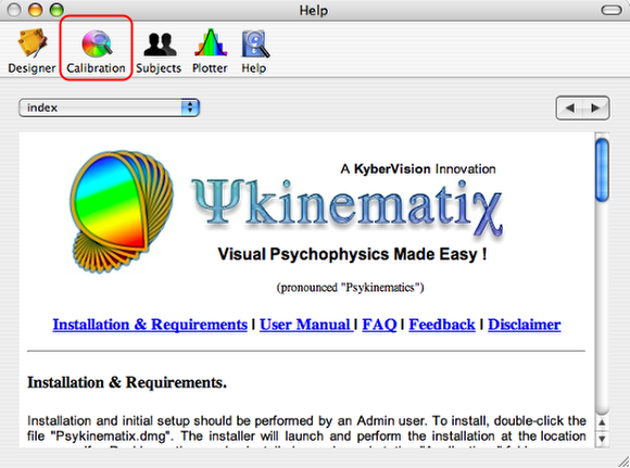
To switch to the Calibration panel from the main panel, click on the Calibration button in the toolbar.
Calibration Panel
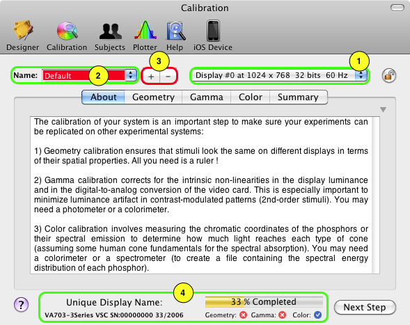
The calibration of your experimental setup requires the calibration of three aspects of the stimulus display: its geometry, its Gamma function, and the color properties of its phosphors. You need a ruler to perform the geometry calibration along with a special device to measure the emission properties of your display (photometer, colorimeter, or spectrometer).
As outlined in green, this panel can manage multiple configurations of a display (1) as well as multiple calibrations for a given configuration (2). In this example, the current calibration is named 'Default', and corresponds to the display at index 0 (this generally refers to the main display) for a resolution of 1024 x 768 pixels in 32-bit mode and with a frame rate of 60 Hz. Note that a 'Default' calibration is created each time a new display configuration is set in the Display Preferences.
3) Click on the '+' button to create a new calibration, named 'NewCal*' by default, and then rename it to better reflect the display type.
4) Note the additional info at the bottom: the unique display name, the calibration progress in % completion and which aspects of the calibration remain to be performed.
Step 1: Geometry Calibration
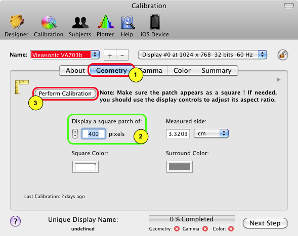
1) Click on the Geometry tab in the Calibration panel.
2) Set the size in pixels of the square patch used to perform the geometry calibration.
3) Click on Perform Calibration.
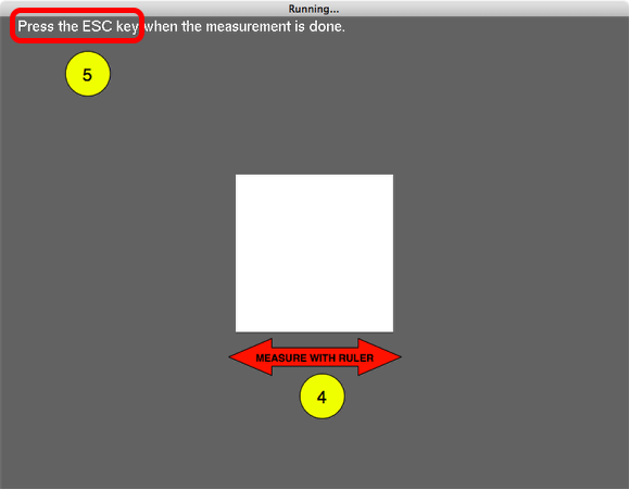
You should see this screen on the stimulus display after clicking on the Perform Calibration button: a square shape displayed in the center in the specified color and size.
4) Use the ruler to measure the sides of the square and make sure it's actually square.
5) Press Esc (escape key) to close the stimulus screen when the measurement is complete.
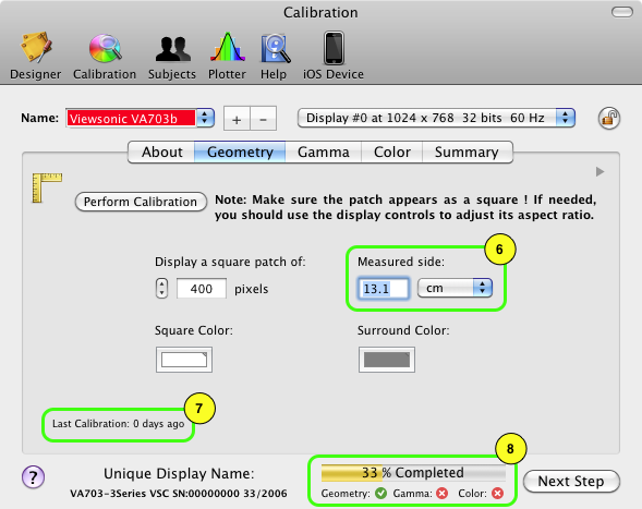
6) Select the measurement unit and enter the measured value in the Measured side field.
7) The time of the last calibration is indicated in the bottom left-hand corner.
8) The completion % is updated with a clear indication that the geometry calibration has been performed.
The geometry calibration is now complete! Click on the Next Step button to switch to the next section of the calibration process.
Step 2: Gamma Correction
To perform a proper Gamma calibration, a device that functions as a photometer is required. Psykinematix interfaces with the Eye-One Display 2 from GretagMacbeth/X-Rite and the Spyder 3 from DataColor (find a list of supported devices in the Calibration Devices section); however, any photometer that displays its readings on a visual output can be used. Finally, make sure your device is set up to produce luminance readings in cd/m^2.
If you don't have access to a photometer, you can still manually set the Gamma value for each gun but your display may not be correctly calibrated.
To perform the Gamma calibration, follow the steps below:
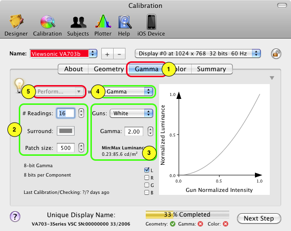
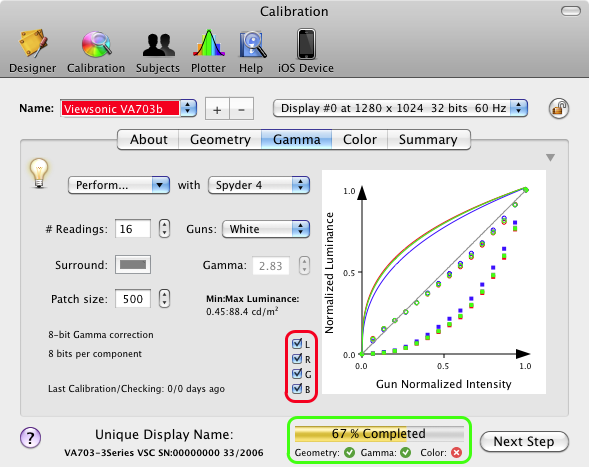
1) Click on the Gamma tab in the Calibration panel.
The stimulus properties (2), and the measurement parameters (3) appear in this panel. The actual calibration is performed after selecting the measurement mode (4) and clicking on the measurement button (5). The plain curve in the graph shows the Gamma of the selected gun.
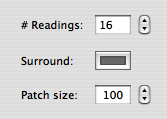
2) Set the number of luminance readings, the surround color, and the patch size in pixels.
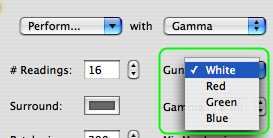
3) Select the gun you want to calibrate: the red, green and blue guns can be calibrated individually or combined to form the white gun. It is advisable to calibrate all 4 guns so the calibration configuration can be used in either the chromatic or achromatic mode set in the Display settings for each experiment.
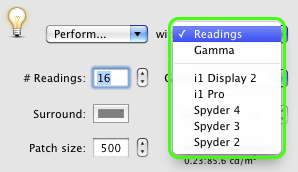
4) Specify the source of the measurement; by default, it is set to Gamma and its value can be directly edited in the field just below. Assuming you have access to a photometer that provides the readings you will enter manually, select the Readings option.
If you have a supported calibration device connected to the computer, select it and the readings will automatically be sent to Psykinematix as you take the measurements.
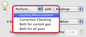
5) Select Gamma Measurement from the Perform... pop-up menu. The Gamma measurement should be performed first, followed by a verification of the linearity of the Gamma correction (Correction Checking).
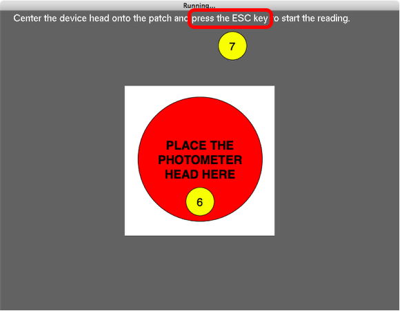
You should see this screen on the stimulus display when selecting one of the Perform... actions: a square shape displayed in the center in the specified color and size, as well as its surround.
6) Place the photometer head in the center of the white square. The square should be larger than the light sensitive area of the photometer; if it is not, press Esc, increase the square size, and re-select Gamma Measurement.
7) To start the measurement process, press Esc when the photometer head is in place.
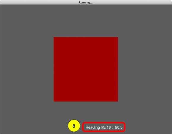
8) In manual mode, enter the photometer reading using the keypad after each change in the square's luminance, followed by the Return key to move to the next luminance level. The reading index and entry are displayed in the bottom right-hand corner of the stimulus display. Use the Delete key to modify the entry before it is validated with the Return key.
When using a supported calibration device, the reading is sent directly to the computer and the next luminance level is automatically displayed. In this case, the reading index is displayed in the top left-hand corner of the stimulus display.
Press Esc to close the screen when the luminance measurements are completed (or press Esc for 1 second to abort the measurement process).
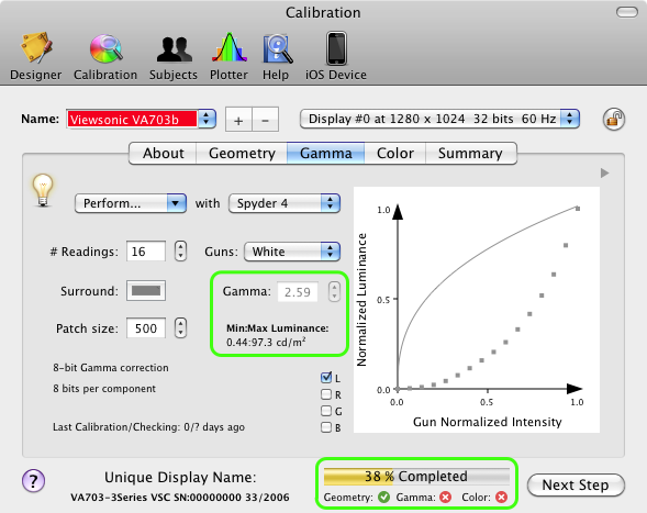
When the Gamma measurement for the selected gun is completed, the graph shows the luminance readings as solid squares.
The Gamma field shows the Gamma value that best fits these data.
The inverse plain curve shows the resulting Gamma correction to be applied.
The graph always shows the normalized intensities, so note the minimum and maximum measured luminance levels indicated below the Gamma field. Contrast and luminance expressed in % in your stimuli properties will be relative to this luminance range.
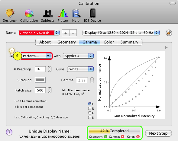
9) The last step of the Gamma calibration is the verification of the linearity of the Gamma correction. Select Correction Checking from the Perform... pop-up menu, and follow the same steps as above to perform the measurement process.
When the checking process is completed, the corrected Gamma is added to the graph as empty circles. The closer they are to the diagonal line, the more accurate the correction is.
Repeat the Gamma calibration for all the other guns, after which the process is complete! Note the updated completion % and the ability to overlap the Gamma data for different guns by clicking on the L, R, G, B check boxes.
It is highly recommended to regularly perform the Gamma calibration of your display (eg. on a daily or weekly basis) and with an appropriate number of readings (higher the number of readings, better the Gamma calibration will be).
Step 3: Color Calibration
For proper color calibration, a device that functions as a colorimeter or spectrometer is required. Psykinematix interfaces with the Eye-One Display 2 colorimeter from GretagMacbeth/X-Rite and the Spyder 3 colorimeter from DataColor; however, any colorimeter that displays its readings on a visual output or any spectrometer with a file output can be used.
If you don't have access to a colorimeter or a spectrometer, you can still set color properties that may be close to your display characteristics, but your display may not be correctly calibrated.
To perform the color calibration, follow the steps below:
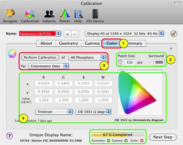
1) Click on the Color tab in the Calibration panel.
The stimulus properties (2), and the measured color properties represented graphically as well as in a table (4) appear in this panel. The actual calibration is performed after selecting the phosphor along with the measurement mode and clicking on the measurement button (3).
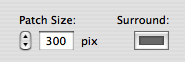
2) Set the surround color and the patch size in pixels.
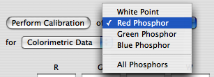
3.1) Select the phosphor you want to calibrate: the red, green and blue phosphors can be individually calibrated or combined to form the white point. It is mandatory to calibrate all 4. If you have one of the supported devices, the 4 can automatically be calibrated in one step by selecting All Phosphors.
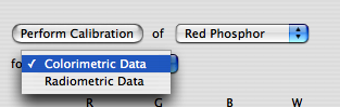
3.2) Select the type of measurement to perform for each phosphor: radiometric or colorimetric properties. For the most accurate calibration, both types of measurement should be carried out.
You need a device with a spectrometer function for radiometric measurements and a colorimeter function for colorimetric measurements.
Colorimetric Data
Select the Colorimetric mode.
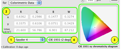
This mode allows you to specify the source of the colorimetric measurement of your display (1) while the measured chromatic properties are presented in the table (2) using the selected CIE standard (4): the chromatic coordinates (xy or u'v') and maximum luminance (Lmax) for each phosphor which form the Maxwell triangle (or gamut) of the display (3) .This chromaticity diagram can be shown either as function of the xy coordinates (CIE 1931 standard) or the u’v’ coordinates (CIE 1976).
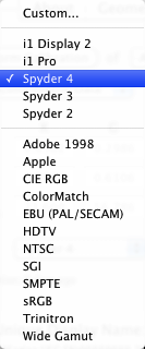
1) This pop-up menu provides several choices. If you own a colorimeter, use one of the top options: Custom... allows you to manually edit the table (2) with readings obtained from a device not supported by Psykinematix while the i1 and Spyder options allows you to automatically obtain the readings from one of the supported colorimeter. Click on the Perform Calibration button to perform the colorimetric measurements for the specified phosphors.
All the other choices in this pop-up menu correspond to various standard displays and should only be selected if you do not have access to a colorimeter AND you are familiar with your display characteristics. On selection of one of these, the table (2) is filled with pre-defined colorimetric data for the specified display type and the gamut is updated (3).
Radiometric Data
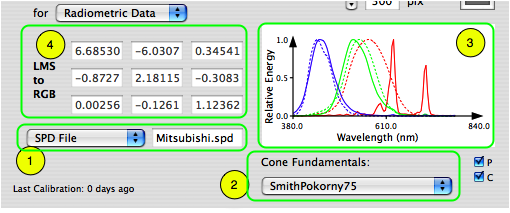
Select the Radiometric mode.
This mode allows you to specify the source of the spectral measurement of your display (1) and the cone fundamentals (2), both shown in the graph (3), in order to generate an LMS to RGB matrix (4).
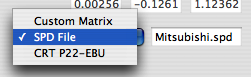
1) The source of the radiometric measurement is specified through a pop-up menu which offers three choices: to produce a custom LMS to RGB matrix by editing the matrix (4), to select a file containing the spectral power distribution for each phosphor, or to select a phosphor standard that closely matches that of your display.
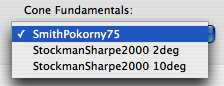
2) The cone fundamentals specify the spectral absorption for each cone and are used in combination with the spectral emission of the display to produce the LMS to RGB matrix which is automatically updated with the selection.
3) The spectral power distributions of both display emission and cone absorption are represented graphically (continuous lines for phosphor emissions, broken lines for cone absorptions) and updated with any change in the selections.
4) The resulting LMS to RGB matrix is displayed in the table and updated with any change in the selections.
Note that Psykinematix does not support any spectrometer yet, but it can import a file containing the data produced by a spectrometer (usually a text file conforming to a specific format described in the documentation). However, Psykinematix can present an appropriate stimulus patch so the spectrometer is able to perform its measurements for each phosphor. To do this, click on Perform Calibration.
Calibration Summary
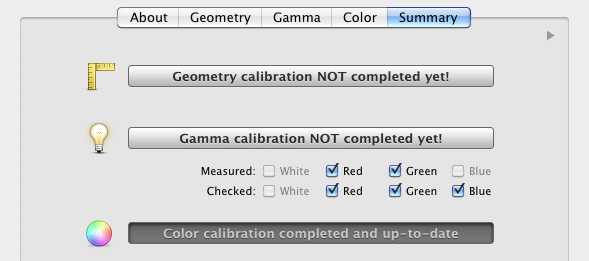
A summary panel is available under the Summary tab which provides an overview of the performed calibration steps. It also indicates that calibration steps that have not been performed yet as illustrated in the example below:
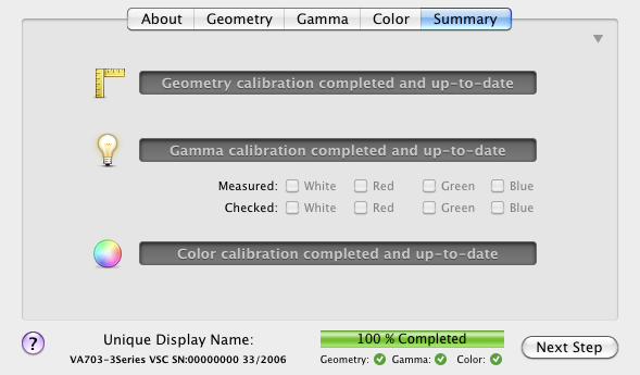
A fully completed calibration should result in the following summary panel:
Specify a Calibration Configuration for an Experiment
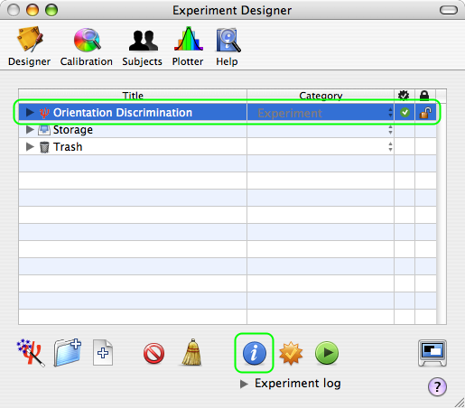
After finishing an experiment design, you should specify the calibration configuration to be used for each session. To do so, select your experiment in the Designer table (Experiment category with the red psi mini-icon), and click on the blue INFO button to inspect or modify its properties.
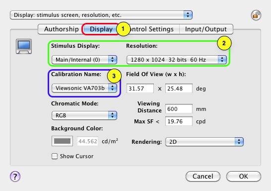
In this properties panel:
1) Click on the Display tab to view/edit the experiment Display settings. By default, the display settings (in particular the stimulus display and resolution) are those defined in the Display Preferences.
2) Select the stimulus display (internal or external) and its resolution (width x height x frame rate) to be used by the currently edited experiment.
3) Select the calibration configuration,
Note that each time the display and resolution settings change, the calibration pop-up menu Calibration Name (outlined in blue above) is updated with all the calibration configurations available for these settings.
If none is available, the selection in the pop-up menu remains blank with a small warning icon attached to it. Click on this warning icon to reset the display settings to the ones in the Display Preferences, or close this panel and return to the Display Preferences and Calibration panel to create a configuration for the new display settings (see beginning of this tutorial).
Conclusion
In this tutorial, you learned how to: calibrate the geometry of your display, measure and linearize its Gamma, measure its color properties, and set the calibration configuration used during an experiment. To learn more about the calibration panel, see the Calibration chapter.